Specification and Description of Work Relating to the Conversion of Ex-Chilean Railways Class 57 Steam Locomotive from Conventional Coal Firing to an Oil Fired Combustion System
Note: Many thanks to Shaun McMahon for providing this copy of his proposal for work on Chilean Class 57 607. Any mistakes contained below are mine.
1. INTRODUCTION
This report is based on the request by Tren del Vino for the conversion of their steam locomotive No.607 from its present coal fired state to an oil burning system. Meetings were held between the company of Tranex Turismo and Fundacion Cardoen on 23rd May 2001 and between 14th and 17th September 2001 relating to this matter. During the time spent by Tranex directors and management at Tren del Vino, the Class 57 was inspected with a view to conversion to oil firing. What is written below is a proposal to put the locomotive in question back to work for the forthcoming season with a completion date intended for June 2002. A brief analysis of the project was completed by the writer on June 21st 2001 and duly presented to Tren del Vino management for their consideration, the meetings held in San Fernando and Santa Cruz during September 2001 were a result of this report.
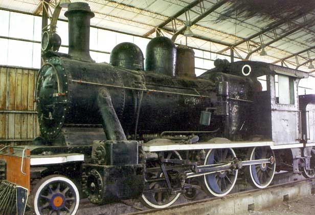
Chilean Class 57 607 in 2001. © Shaun McMahon
2. GENERAL CONSIDERATIONS
The aim of this project is to provide Tren del Vino with a steam locomotive in reasonably good and safe working condition (relative to its present state) in time for it to enter regular traffic during June 2002. In order to achieve this aim it is proposed to attend to the following areas, in order of priority, during this project:
At this point in time it is convenient to define the work in hand as a form of examination related to an existing international code of practice. The proposed work (excluding conversion to oil burning) coincides mainly with an Indian Railways Schedule III examination.
The work in hand has been separated into 2 different sections - Section 3, which has been further broken down into sub sections, deals with Boiler, Mechanical and General. Section 4 describes in detail the conversion to oil burning. It is convenient to consider this examination and modification as a first stage of work, being followed up by a second stage of work based on the results of a) work carried out at stage 1 and b) performance of locomotive in traffic following examination and modification. At Tranex, with respect to Ferrocarril Austral Fueguino (FCAF), it has been found that this approach makes sound technical and economic sense when dealing with steam locomotive overhaul and modification projects - good examples of such are FCAF locomotives No. 3 'Camilla' and No.2 'Nora' which have undergone first stage heavy overhaul and modification during 1999 and 2001 respectively. A second stage of overhaul and modification would deal with all areas in much more detail. Whilst the form of the Class 57 locomotive would not change in any way, it should be recognised that the shape of some components or areas will change as a result of modification work that is required in order to convert the engine to burn oil successfully rather than coal or oil unsuccessfully. Tranex is well aware that the form of the Stephonsonian steam locomotive is very important as part of its general, and more specifically emotive, appeal to the public and during all modification work carried out by the company the aim has been to keep the form as attractive and authentic as possible. However in a developing world where safety and environmental restrictions are becoming increasingly more rigid by the day, no business can afford to be purist in its attitude towards working machinery. The most noticeable changes in the appearance of the Class 57 would be: fuel tank positioned in the space formerly taken up by coal, appearance of panplate and primary air intake 'trumpets' below foundation ring level, altered firehole door, oil firing control gear inside cab on left hand side and altered shape of chimney.
Limits and fits of mechanical components shall be to the standards set down in the Locomotive Manufacturers Association Handbook (first edition 1949). Boiler work shall be carried out to the standards set down in the American Society of Mechanical Engineers code of practice (section referring to locomotive boilers). All work shall be based upon designs drawn up and approved by the Technical Projects Manager, Tranex Turismo S.A. Where guaranteed accuracy of modified components is required so as to ensure predicted performance of the locomotive in traffic, these will be contracted out to a manufacturer that specialises in such work. This report is written with the assumption that the Class 57 locomotive will burn gas oil as a fuel rather than any other grade of fuel oil as referred to in the brief report of June 2001. This matter must be confirmed before design work begins, as the design parameters for a gas oil system are different to that required for a heavier fuel oil.
It must be stressed that all descriptions and specifications are based upon the work in hand being undertaken by professional and skilled engineering personnel. Tranex is not responsible for consequences that result from the deviation of this policy.
3. DESCRIPTION OF PROPOSED WORK TO BE CARRIED OUT BY TRANEX TURISMO S.A. IN CONJUNCTION WITH PUTTING No.607 TO WORK SAFELY AND RELIABLY
3.1 BOILER
3.1.1 Remove cladding sheets from boiler barrel and outer firebox. Remove lagging and store with cladding sheets. Remove all boiler fittings, boiler washout plugs and fusible plug. Remove dome cover. Wire brush exterior of barrel and outer firebox. Carry out full visual 'cold' examination of boiler barrel exterior. Carry out visual examination of water spaces using inspection and washout access holes and dome. Inspect mechanical function of regulator.
3.1.2 Thoroughly clean inside and outside of smokebox, ensure smokebox interior is wire brushed to 'bright metal' state. Carry out visual examination of smokebox interior and exterior.
3.1.3 Remove ashpan. Thoroughly clean inner firebox; finish to bright metal state. Visually inspect inner firebox paying particular attention to crown and side sheet stays, thermic syphons and foundation ring.
3.1.4 Carry out visual examination of outer firebox paying particular attention crown and side stays.
3.1.5 Remove existing fusible plug. Extract existing lead in plug body. Inspect body for general condition and replace as required, ensure old body is scrapped if this is the case. Re-lead fusible plug to South African Railways Code of Practice Part 3 Boiler building and Repair Practice, Clause 3A. 1201,1202,1203,1204,1205,1206. Manufacture 2 spare fusible plug bodies to specification supplied by Tranex and put in storage at San Fernando Motive Power Depot. DO NOT lead these plugs. Date stamp the renewed plug before inserting in crown sheet boss.
3.1.6 Prepare boiler for hydraulic test by blanking off all boiler fitting flanges. Refit dome cover. Fit main boiler pressure gauge in position. Hydraulically pump the boiler up to a pressure of 1,5 times its normal working pressure, in this case 1,5 X 180 lbf/square" = 270 lbf/square". Maintain this pressure for half an hour. During this period of time inspect the boiler completely for any sign of leakage.
3.1.7 All of the above inspection work is to be carried out by a qualified boiler inspector and certified boilermaker in the presence of the Technical Projects Manager, Tranex Turismo S.A.
3.1.8 Formulate plan of repair work to be carried out to the boiler as a result of both cold visual and hydraulic examinations.
3.1.9 Carry out full visual examination of all existing boiler fittings so as to ensure such are safe to be used during steaming conditions. Design and manufacture boiler fittings which do not exist at this moment in time. Design and install a second boiler water gauge column in order to replace the present test cock arrangement. Design and fit 4 off mounting studs to backhead, which will accommodate new oil firing type of firehole door (see section 4). Following any required repair or renewal work, carry out a second hydraulic examination to 1,5 X working pressure for a period of half an hour. If successful, renew boiler lagging and cladding.
3.1.10 Fit dome cover and all boiler fittings.
3.2 MECHANICAL
Note: When reference is made to individual components below, such applies to right-hand and left-hand side of the locomotive.
3.2.1 Mainframe - Carry out visual examination in order to check for cracks misalignment and general condition of frames.
3.2.2 Valve gear - Remove valve gear. Inspect all pins and bushes for wear and general condition, renew such as necessary.
3.2.3 Motion - Remove connecting and coupling rods. Inspect crank pin surface for lubrication conditions (i.e. the film of lubricant that is evident on the pin). Measure crank pins for ovality. Measure rod end bearings for wear and general condition, renew as necessary. Inspect connecting and coupling rods for general condition. Remove crosshead and inspect for wear and general condition. Renew crosshead slippers if wear is in excess of tolerable limits. Inspect gudgeon pin for wear and general condition; renew if wear is in excess of tolerable limits. Inspect piston rod/crosshead taper cotter for wear and general condition, renew as necessary.
3.2.4 Valves and pistons - Remove cylinder and valve chest covers. Remove pistons and valves. Inspect pistons and valves for wear and general condition. Inspect piston and valve rings and renew as necessary. Inspect cylinder liner for surface lubrication condition, inspect for general condition. Inspect cylinder liner for internal ovality by measuring internal diameter at specified points along and around such. Inspect valve liner for surface lubrication condition, inspect for general condition. Inspect valve liner for internal ovality by measuring internal diameter at specified points around and along such.
3.2.5 Reassemble upon completion of work (in sequential order): Pistons, valves, crosshead, coupling rods, connecting rods, valve gear, cylinder covers and valve chest covers. Check setting of valve gear.
3.2.6 Visually inspect leading bogie for general condition - wheel profile, wheel condition, axle condition, axle box condition, lubrication, suspension, side control gear.
3.2.7 Driving wheels -Visually inspect wheels for general condition. Examine tyres for tightness on wheels (sound test) and measure tyre profile, compare with specified profile as designated by the respective drawing. Visually inspect driving axle springs, hangers, compensating beams and pins for general condition. Visually inspect axle boxes, box guides, shoes and wedges for general wear and condition.
3.2.8 Brake gear - Visually examine brake blocks for wear, condition and setting. Examine brake gear operating linkage for general condition. Examine hand brake screw for operation and condition.
3.2.9 Tender - Visually examine: wheels and axles, axle boxes, box guides, springs and compensating beams along with associated pins and bushes. Inspect wheel profile. Visually examine brake blocks, brake gear linkage along with associated pins and bushes. Visually examine mainframe of tender.
3.2.10 Draw gear - Visually examine locomotive and tender draw gear for security and operation. Inspect locomotive and tender safety chains for general condition. Visually examine locomotive/tender draw gear for general condition.
3.2.11 Fit locomotive with mechanical lubricator. Design the pump drive to feed oil to pistons, valves, piston rod gland, valve rod gland and slidebars in proportional form. Drive to be taken from valve spindle hence feed rate is proportional to percentage cut off.
3.3 GENERAL
3.3.1 Air pump -Remove air pump from locomotive. Strip down pump, beginning at top (steam end) working methodically downwards towards the lower cylinder (air end). Examine both steam and air cylinder liners for wear and lubrication conditions. Inspect steam and air side piston heads for general condition. Examine piston rings (both sets) for wear and general condition and renew as necessary. Examine air pump mounting bracket for general condition. Reassemble pump and remount on locomotive.
3.3.2 Footplating - Visually examine all interior and exterior footplating for security and general condition; repair badly damaged or corroded sections as necessary.
3.3.3 Cab and tender plate work - Visually examine for general condition and repair/renew badly damaged or corroded sections as necessary (cut out such sections, clean and weld in butted position new plate).
3.3.4 Electrical - Remove turbo generator from locomotive. Place on bench and carry out full examination. Rotate the generator using air rather than steam so as to test function, connect to locomotive electrical system so as provider load and at the same time test the function of the electrical system as fitted. Reassemble and replace on the boiler mounting brackets. Fully examine headlights, cab lights, gauge column light; repair/renew as necessary. Examine electrical circuit and conduit; repair/renew as necessary. Examine terminal and switching boxes. It was noted during the preparatory examination of the locomotive on 15th/16th September 2001 that the former operators of this locomotive had adopted a particularly bad practice involving running the electric cables inside the boiler mounted handrails. Such should be removed from this position and replaced by dedicated conduit.
3.3.5 General appearance of locomotive - At this stage of the work it is intended to carry out minimum work in this area, however it should enter revenue-earning service in an acceptably presentable form. Thoroughly clean all parts of the locomotive. Repaint certain components and areas of the locomotive that appear to be in non-presentable condition.
3.3.6 Tender water space - Thoroughly inspect water space for corrosion of structural sheets and baffles. Repair using backing plate as necessary. Visually examine feed water reservoirs for corrosion, repair as necessary.
3.3.7 Air braking system and fittings - Visually inspect all air supply pipework for general condition inclusive of flexible pipes between engine, tender and train. Visually inspect all air braking fittings on engine and tender, repair and replace as necessary. Visually examine (exterior and interior) all air reservoirs.
4. CONVERSION OF CLASS 57 LOCOMOTIVE BOILER FROM CONVENTIONAL COAL TO OIL FIRING
As this work constitutes the basis of the initial request by Tren del Vino for Tranex Turismo S.A. to become involved with this project, a separate section is devoted to describing the work, which may be noted as being nothing less than a major modification and technological advance as far as steam locomotive engineering is concerned. The below system is fitted to Tranexs' FCAF steam locomotive No.2 'Nora' and thus the system can be demonstrated in operation on a daily basis at Ushuaia. Likewise 'Nora' could be used as a training locomotive for Tren del Vino drivers and firemen so to familiarise them with oil firing conditions. FCAF locomotive No.3 'Camilla' is also fitted with an oil burning system, however at the time of writing it still retains its 'trough' (flat) type burner and is therefore does not provide a direct comparison with the type of system that is proposed for 57 Class No. 607.
4.1 BURNER
4.1.1 Design rotary, internal atomising type oil burner.
4.1.2 Manufacture rotary burner.
4.2 FIREBOX ARCH.
4.2.1 Design steel firebox arch. Such to be used to form combustion chamber in upper part of firebox. Arch to be manufactured from ATSM 310 S or ATSM 330 (to be defined at design stage). Thermic syphons may be used as arch supports once steel is defined, however, crown supports along with side wall carriers will be used in this particular case.
4.2.2
Manufacture steel firebox arch.
4.2.3 Manufacture side wall arch carriers. Steel to be defined
during design stage.
4.2.4 Manufacture crown supports. Steel to be defined during design stage.
4.3 PANPLATE
4.3.1 Design firebox panplate. This will replace conventional coal firing grate and ashpan. 10 mm steel plate to be used for this component. Panplate to be boxed in with refractory concrete to a depth of 150 mm Burner to be placed central surrounded by primary air intakes. Panplate may be designed as a 4 piece component rather than 1 piece depending on available space for fitting below the firebox.
4.3.2 Manufacture firebox panplate.
4.4 REFRACTORY WALL
4.4.1
Design refractory brick wall to cover lower section of all inner side sheets
of inner firebox. Height of wall to be determined at design stage. Thickness
of wall to be 100 mm
4.4.2 Manufacture refractory brick mould.
4.5 FUEL OIL CONTROL VALVE
4.5.1 Design fuel oil control valve and adjoining operating stem, handle and quadrant.
4.5.2 Manufacture fuel oil control valve and fit in position along with operating stem and quadrant.
4.6 OIL FIRING STEAM MANIFOLD
4.6.1 Design steam collecting manifold for use in conjunction with oil firing apparatus. Such should be provided with connection for compressed air fitting (light purposes when locomotive is out of steam), drain and connections for main steam supply from turret (also acts as shut off isolating valve), atomiser and blower control valves.
4.6.2 Manufacture oil firing steam collecting manifold. Pressure test and fit to locomotive boiler by means of mounting bracket. Positioning of this manifold and operating valves (as is the fuel oil operating handle) are critical to the ease of operation of this locomotive by the fireman. Instruction notes will be issued as part of the design stage (4.6.1) and such must be followed.
4.6.3 Select stainless steel seated steam operating valve for supply and fine control of burner atomising steam. Select stainless steel seated steam operating valve for supply and control of blower steam. Purchase, along with spares, and fit to locomotive oil firing steam collecting manifold.
4.7 FIREHOLE DOOR
4.7.1 Design oil firing type firehole door in order to replace coal firing type currently fitted to the locomotive. Such should include provision for full swing in order to allow for firebox visual inspection and access. Should include peep hole and tube to allow for safe light up of fire, periodic inspection of flame brightness and tube sanding.
4.7.2 Design firehole door mounting frame, such must fit onto the mounting studs as provided (see 3.1.9).
4.7.3 Fit firehole door and mounting frame to locomotive.
4.8 FUEL OIL PRE HEATER
4.8.1 Design normal type fuel oil pre heater if type of fuel to be used is not gas oil. Design moderate temperature type of fuel pre heater if fuel oil is to be gas oil.
4.8.2 Manufacture fuel oil pre heater.
4.9 PRIMARY AIR PRE HEATER
4.9.1 Design primary air pre heater.
4.9.2 Manufacture primary air pre heater.
4.10 FUEL OIL DRAIN VALVE
4.10.1 Select 90 degree valve suitable for draining fuel oil.
4.10.2 Purchase 90 degree valve.
4.11 FUEL OIL FILTER
4.11.1 Design/select commercially available fuel oil filter.
4.11.2 Manufacture/purchase fuel oil filter.
4.12 OPERATING PRESSURE GAUGES AND TEST GEAR
4.12.1 Select suitable pressure gauges for measuring atomising steam (air if in cold out of steam state) pressure and blower steam (air if in cold out of steam state) supply pressure.
4.12.2 Purchase pressure gauges (4.12.1).
4.12.3 Design manometer water gauges in order to take readings of smokebox vacuum and firebox vacuum values.
4.12.4 Manufacture manometer water gauges (4.12.3).
4.12.5 Select suitable flow meter in order to take readings of flow rate between oil control valve and burner, such should be able to register a permanent record and a re settable record of fuel oil supplied to the burner.
4.12.6 Select suitable pressure gauge to measure steamchest pressure.
4.12.7 Purchase suitable gauge (4.12.6).
4.12.8 Design sensor and mounting that will fit into blast pipe in order to read steam pressure that will be representative of total back pressure.
4.12.9 Select suitable pressure gauge that will be able to take readings of total back pressure.
4.12.10 Purchase suitable pressure gauge (4.12.9) along with copper and flexible pipe that will conduct steam sample from blast pipe back to cab fitted display.
4.12.11 Manufacture sensor and mounting that will fit into blast pipe at a designated point between Kordina and Lempor manifold.
4.13 ASSOCIATED PIPEWORK AND FITTINGS FOR OIL FIRING SYSTEM
4.13.1 Select, upon the basis of the design work carried out for section 4, suitable pipework that will supply fuel oil and atomising steam to the burner, main shut off valve for the fuel oil tank, pipework that will supply steam from the main turret to the oil firing manifold and connecting fittings that allow all to be joined in a safe and efficient manner.
4.13.2 Purchase items relating to 4.13.1
4.14 ATOMISING STEAM SUPERHEATER
4.14.1 Design atomising steam superheater.
4.14.2 Manufacture atomising steam superheater.
4.15 LEMPOR EXHAUST MANIFOLD
4.15.1 Design Lempor exhaust manifold, such to include integral blower ring cast into base and 4 off stainless steel Delaval blower jets that will screw into the cast base.
4.15.2 Manufacture Lempor exhaust manifold.
4.16 KORDINA
4.16.1 Design Kordina.
4.16.2 Manufacture Kordina.
4.17 EXHUAST MIXING CHAMBER AND DIFFUSER (CHIMNEY)
4.17.1 Design Lempor exhaust mixing chamber and diffuser. 5 mm plate to be used throughout. To include swing top, air tight, chimney lid and mechanism.
4.17.2 Manufacture Lempor exhaust mixing chamber, diffuser and swing top, air tight chimney lid.
4.18 EXHAUST STEAM PIPES
4.18.1 Design new exhaust steam pipes. These should allow the exhaust steam to flow via the most direct and largest cross sectional route between the cylinder outlet and Kordina entrance throat. It is noted that the existing exhaust steam pipes are of a particularly poor configuration due to the positioning of the leading bogie and the fact that the centre line is displaced from the centre line of the chimney in the leading direction by a distance of 245 mm This is likely to be have been caused by a design change when the boiler was modified to incorporate superheating i.e. the superheater header occupying the free space that was available between the front tubeplate and the chimney petticoat. There are 2 ways of overcoming this problem which will described in detail as part of the design notes at a future stage. Fabrications to be used throughout.
4.18.2 Manufacture steam pipes and connecting flanges.
4.19 FUEL OIL TANK, MOUNTINGS AND FITTINGS
4.19.1 Design fuel oil tank. Such to include internal baffle plates, manhole, filler, mounting base, mounting brackets and fixings, rigid supply pipe, main shut off valve and fuel capacity gauge. The design of the tank should take into account the fact that width is restricted by the siting needs of the crew when working the engine in reverse direction (though turntables are used on this line there are critical times during the operation, such as coupling the locomotive to the train, when the driver needs to be able to see clearly in the reverse direction). Overall height is restricted by the loading gauge. The easiest possible method of filling and checking fuel capacity should be available to the crew hence the filling point and capacity gauge should be as near to the cab access as is possible with steps and handrail being provided in order to climb up to this point in the safest and easiest manner. 5 mm plate to be use throughout. Carry out tank leakage test, inclusive of main shut off valve.
4.19.2 Manufacture fuel oil tank.
4.20 TRADITIONAL CHIMNEY PARALLEL COVER
4.20.1 Design chimney cover that will fit easily over the Lempor diffuser and form a rounded cap and base. It should be noted that this component is purely cosmetic and plays no active part in the conversion of the locomotive to oil firing. Likewise the cover should not in any way interfere with the design parameters of the Lempor diffuser which would compromise the efficiency of the oil firing system. 5 mm plate to be used throughout.
4.20.2 Manufacture chimney cover.
4.21 ASSEMBLY AND FITTING OF COMPONENTS TO LOCOMOTIVE
NOTE: Prior to assembly procedure the ashpan, smokebox door, chimney, table plate, blast pipe and exhaust steam pipes should all be removed.
4.21.1 Weld in position arch crown supports.
4.21.2 Weld in position side wall arch carriers.
4.21.3 Fit panplate to foundation ring.
4.21.4 Place refractory wall mould in position. Insert corrugated cardboard around wall face and cast refractory wall.
4.21.5 Fit steel arch in position.
4.21.6 Fit burner to panplate.
4.21.7 Mount fuel oil tank in tender and fit in position.
4.21.8
Fit main shut off valve to fuel tank supply line.
4.21.9 Fit burner atomising steam superheater.
4.21.10 Fit oil firing steam manifold to boiler.
4.21.11 Connect oil firing manifold to steam turret. Fit steam valves for atomising and blower steam supply. Fit drain valve. Connect manifold to atomiser superheater. Connect blower steam supply valve to smokebox. Fit pressure gauges to atomiser and blower steam supply lines.
4.21.12 Connect fuel tank oil supply to fuel oil heater.
4.21.13 Connect fuel oil heater to fuel filter.
4.21.14 Connect fuel filter to fuel oil control valve.
4.21.15 Connect fuel oil control valve to fuel oil drain valve
4.21.16 Connect fuel oil drain valve to burner.
4.21.17 Connect superheater to burner.
4.21.18 Fit primary air heater to locomotive.
4.21.19 Fit exhaust steam pipes.
4.21.20 Fit Kordina.
4.21.21 Fit blast pipe to Kordina.
4.21.22 Fit Lempor mixing chamber and diffuser. Use French method for lining up blast pipe to chimney.
4.21.23 Fit Lempor exhaust manifold.
4.21.24 Connect Delaval blower ring to steam supply from oil firing manifold.
4.21.25 Following a period of testing in service, fit outer chimney parallel cover.
5. CONCLUSIONS
This report forms the basis for a budget proposal from Tranex Turismo S.A. to Fundacion Cardoen, owners of Tren del Vino. As stated in the brief initial report of 21st June 2001, some components should be manufactured in Argentina whilst others should be manufactured in Chile. As many of the original drawings of the Class 57 type of locomotive should be made available for the design stages of this work. Work on the project should begin at a convenient date following the full completion and testing of Tranexs' FCAF locomotive No.2 'Nora'. The Technical Projects Manager, Tranex Turismo S.A. or his deputy should undertake supervision of the work in hand at San Fernando. The work described in this report does not include a specification for 'tooling up' in preparation for such; this is outlined in a separate appendix.
S.
McMahon
Technical & Technical Projects Manager
Tranex Turismo S.A.
Ushuaia
Tierra del Fuego
Rep. Argentina
2nd October 2001.