
Converting Mount Washington No.9 to Biodiesel Fuel
The World's First Biodiesel Fuelled Steam Railway Locomotive
The last update to these pages on Nigel Day's Mount Washington Cog Railway work was way back in April 2005. The gap does not indicate a lack of progress, rather the work undertaken since then has been ground-breaking. It was felt until things were "right" it was best to say nothing during the development phase than provide an occasional update on the experimental work in progress. As can be expected with any such work there have been good days and bad days but Mount Washington No. 9 'Waumbek', affectionately referred to as Vicki (as in victim!) has become the first steam railway locomotive in the world fired on biodiesel, thus becoming effectively carbon neutral.
Nigel's contract with the Mount Washington Cog Railway came about as a locomotive which can be fired with a liquid fuel was wanted by the line. As the previous years of work show a staged approach to the project was taken rather than a "big bang", all done at the same time, conversion. There are very good reasons behind this. It has allowed plenty of data collection in a "before" state to be gathered, general experience of the locomotives type could be built up and experience and knowledge of modern steam technology could be gained by Mount Washington staff. It is perhaps not generally appreciated what a jump in technology it is to go from a "normal" type of coal burning loco to a modern design of liquid fuel burner. Whilst such burners are designed to be as idiot proof as possible it is true that an approach based on "hitting it with a hammer" to get it working is not going to work!
The Mount Washington line has previously, unsuccessfully, experimented with liquid fuels showing how difficult it can be to make a liquid fuel system work effectively on steam locomotives. The previous failures can be attributed, in part, to the application of inappropriate technology to the test locomotives. However there is also the issue of the extremely high combustion rates required to match the demand for steam. For locomotives of this size the evaporative rates are somewhat higher than for adhesion locomotives. A combustion system to match these requirements in the small volume firebox needs to be very carefully designed if it is to burn cleanly and without waste, if it can meet the requirements at all. In practical terms the system has to be better than any other conventional system.
One previous attempt to implement liquid fuel at Mount Washington. This is loco 'Great Gulf' experimentally fitted with oil firing in 1938. Quite why the loco retains a spark arrestor cage on top of the chimney is uncertain. Photo Boston Maine, courtesy of Nigel Day |
 |
 |
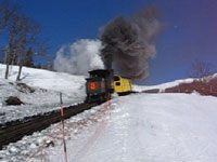
A look back to 2004. A typical train on the Mount Washington Cog Railway starts away for the summit producing a column of smoke. All unmodified locos ascend the mountain emitting vast clouds of smoke. Money up the chimney in no uncertain way! © Nigel Day |
In contrast to the photo above this image from May 2006 shows No.9, then on test, setting off smokelessly. Smoke free combustion continues all the way to the summit in normal service. © Nigel Day |
 |
 |
New and old side by side at the Mount Washington workshops. No.9 with its new form of chimney and other modifications stands alongside No.4 which remains in totally unmodified form. © Nigel Day |
The Fuel Source
The term 'biodiesel' is one which has recently come into fairly common usage but unlike 'diesel' it is a less rigidly defined term. Diesel is a very much standardised product with very little variation across the world. But biodiesel, whilst approximately the same, covers a range of products from various sources. For example some biodiesel is produced from waste vegetable oil used in cooking etc but other sources will be produced direct from crops such as rape seed (Canola) or many other forms of biomass.
The Main Burner
The burner is of a modified design based on Nigel's previous round flat burner for mineral diesel fuel. The characteristics of biodiesel are somewhat different to fossil diesel hence the need for a modified burner. It really is not a simple case of filling up with biodiesel and off you go. To effectively burn liquid fuels requires, at the very least, the burner settings to be altered to suit the fuel characteristics and more likely, as in this case, that a modified (or even a totally new) burner will be required.
As in Nigel's previous liquid fuel systems the fuel is fed by gravity to the burner. There is never any need for fuel pumps. The only requirement is that the fuel tank height above the burner remains above a certain level to maintain the gravity flow. As can be appreciated this can be difficult on rack locos, especially those with tenders. When fired on coal the Mount Washington locomotives force the fireman to fire uphill, that is the tender is somewhat lower than the firehole. However despite this it has proved possible to mount the fuel tank at a sufficient height above the burner and to do so without radically altering the overall appearance. The fuel tank is sufficient for two round trips between refilling. Coal fired locos re-fuel after one round trip.
The panplate. This view shows the topside with the hole for mounting the burner prominent in the centre. The two slots are provided to allow the atomising steam superheater elements to be fitted. In due course the space between the air pipes etc was filled with fireclay. © Nigel Day |
 |
 |
The burner, made from stainless steel, is mounted centrally in the square firebox. It sits in the middle of a specially constructed panplate. This panplate replaces the grate used when coal fired. Incorporated into the panplate are a large number of tubes which direct combustion air into the firebox. The arrangement and number of tubes is not random but designed in such a way as to ensure that not only is there sufficient combustion air, with the minimum of excess air, but that the flow ensures excellent mixing of the fuel and air in the firebox thus giving clean and complete combustion. The burner is feed the fuel under gravity but once in use a partial vacuum is created by its own action thus assisting in the fuel feed. In line with Nigel's previous burners atomising steam is also feed into the burner, that is atomising of the fuel occurs internally to the burner. Atomising the fuel effectively is perhaps the single most important stage in ensuring good combustion. The greater the degree of atomisation the higher the effective surface area of fuel and thus the easier it is to ensure it all burns. Most previous oil firing systems the world over have relied on external atomisation, that is the fuel and atomising steam mix outside of the burner. In some cases the heat in the firebox has been relied on to atomise the fuel. Such an approach makes it nigh on impossible to achieve good atomisation and leads to poor combustion. This is one reason many oil fired locomotives, even today, are extremely prone to large emissions of smoke. Traditionally atomising steam has been taken from the locomotive's manifold and fed directly to the burner. In other words it is fed with saturated steam. Just as for use in locomotive cylinders there are benefits with liquid firing in using superheated steam. In short more energy is held by a unit weight of steam meaning less steam is required to do the same job. As superheated steam is hotter it has the additional benefit of pre-heating the fuel prior to its ejection into the firebox. The closer the fuel temperature is to the fire temperature the better, less energy is wasted in heating the fuel to the necessary temperature by the fire itself. The use of superheated atomising steam has shown a fuel saving of between 5-10% is possible. The Mount Washington locomotives are purely saturated steam locomotives. So how can superheated steam be provided? The answer is a simple one. The layout of the steam circuit is irrelevant. Atomising steam is still fed directly from the manifold in saturated form. It is superheated on its way to the burner. This is achieved very simply by passing loops of suitable grade steel through the firebox space. By doing so the action of the fire on these superheater elements is to superheat the steam passing through them. This superheated steam then enters the burner, mixes with the fuel and atomises it. |
Once atomised the fuel is ejected from the burner at the top through the emission gap, another item needing careful attention to get good performance. The spray of fuel is directed out horizontally across the firebox. This is done to make use of the full grate area, ensure good fuel/combustion air mixing, provide sufficient time for combustion and also, importantly, to as closely mimic as possible the action of a coal fire. Locomotive boilers are designed for "flat" fires so why alter this fundamental feature? Experience has shown vertical burners of a type directly copied from other branches of industry just don't work too well in locomotive applications and are far from good for the long term structural integrity of the boiler.
 |
Main fuel flow control valve. © Nigel Day |
One advantage associated with burning fuels in as close to the theoretical optimum conditions as possible is the reduction in soot formation and thus the lining of the firebox and boiler tubes with a layer of insulative soot. Such conditions have rarely existed on locomotives. It is traditional therefore that sand is poured into the firebox as prescribed intervals. This sand is sucked, by the action of the smokebox vacuum, through the tubes effectively scouring them clean - in a coal fired loco firebed particle carryover keeps the tubes clean, except where excessive causing tube blockage! This sometimes overlooked fact gives the lie to the comment that using sand to scour the tubes is an awful, harmful practice. Whilst this procedure is not entirely removed with this new burner the amount of soot which collects is very substantially reduced. It is normal practice to pour 1/2 a cup of sand into the firebox on each trip. No liquid firing system yet developed removes the need to clean the tubes in this way despite some thinking they have, a point Porta used to insist on making.
A problem associated with liquid fuel firing has been that of flame impingement on the firebox walls. With this type of burner the problem is considerably reduced over previous generations of burner but it is not entirely eradicated. So a thin layer of fireclay is required at the bottom of the firebox. Once up to temperature this sacrificial fireclay does little to impinge on heat transfer rates. The fireclay is cast in sheets for the purpose.
Despite the small volume of the firebox a combustion arch, again of cast fireclay sheets, is fitted to assist the combustion process.
A view into the firebox. At the top can be seen the combustion arch. Below this on the blackened walls of the firebox are several thermocouples attached during the testing, tuning and acceptance process. Prominent is one of the pair of atomising steam superheater elements. The other is in the mirror image position. Note the double-wall thickness close to the panplate where the elements are directly in contact with flames. As can be seen the panplate itself is filled with fireclay. © Nigel Day |
 |
In the cab there are a number of additional controls and gauges. A specially made valve to graduate the fuel flow sits prominently in front of the fireman's seat. Also in front of him is the atomising steam valve and gauges showing the atomising steam pressure and blower pipe pressure.
 |
This is what the fireman sees. Towards the bottom left is the fuel flow control valve. Above this are the gauges showing the atomising steam pressure and blower pipe pressure. The atomising steam control valve is located above the gauge, out of view in this image. This photograph was taken during the early days of testing hence the coil of cables and the gauge sat on wooden blocks above the fuel flow valve. © Nigel Day |
Fireman Mark Sodergren adjusts the atomising steam during testing. Note the manometer in front of him measuring vacuum levels at various points on the locomotive. © Nigel Day |
 |
 |
A contrast in combustion efficiency! Taken in the morning as pressure is raised on biodiesel fuelled No.9 and coal fired No.2. © Nigel Day |
The Lempor Exhaust Ejector
The Lempor arrangement has been tuned to suit the fuel. Just as different fuels require different combustion conditions to get the best out of the exhaust ejector it is necessary to tune the arrangement to the fuel type. At the same time the opportunity was taken to remove the diamond stack type chimney, replacing it with one of a more conventional appearance. Naturally the smokebox mounted spark arresting equipment has been removed. It is simply no longer necessary. The removal of these various items of equipment further alters the resistance to gas flow thus altering the draughting requirements.
 |
The spark arrestor free smokebox with the biodiesel Lempor arrangement in place and partially rigged for testing. © Nigel Day |
The new chimney has a feature ALL locomotives, regardless of fuel type, should have - a chimney cap. This is put in position any time the fire is out. The use of chimney caps has been shown to have very considerable benefits to the boiler by considerably slowing down the rate of cooling, it also reduces standby losses by a useful amount.
No.9 during testing in 2007. © Nigel Day |
 |
Testing, Tuning & Acceptance
The locomotive was ready for testing in May 2006. Initial results were very encouraging with the locomotive more or less performing as required from day one. Of course there were things to tweak and tune but for a first attempt to run on biodiesel the results were excellent.
When the locomotive is cold and there is no pressure in the boiler an air line is used to replace the atomising steam allowing the fire to be lit. The line can be seen connected to the locomotive on the boiler side above the cylinders. © Nigel Day |
 |
Extensive performance monitoring has been undertaken, perhaps more detailed than any other similar work yet undertaken. In addition to the normal sets of tests relating directly to component performance, steam temperatures, fuel and water consumption etc interest centred on firebox wall temperatures. The data confirmed much work previously undertaken whilst also showing that many advances have been made over previous work.
 |
Cables everywhere - No.9 during the measurement of a large number of parameters. © Nigel Day |
A view back over the tender on No.9. Following someway behind and at a slower pace is a coal fired loco displaying the normal awful combustion of these locos in original form. © Nigel Day |
 |
Biodiesel Burner Video Clips |
And For Comparison.... |
|
Main Burner Operation |
Locomotive Operation |
A Locomotive on Coal Fuel |
 |
 |
 |
41 seconds in duration. Windows Media Video format: © Nigel Day |
56 seconds in duration. Windows Media Video format: © Nigel Day |
18 seconds in duration. Windows Media Video format: © John Johnston |
No.9 at the summit station on the Mount Washington Cog Railway during an early trial run in May 2006. Note that the chimney cap is in the closed position. © Nigel Day |
 |
After much work No.9 was finally given permission to run in ordinary service by the New Hampshire State authorities in June 2007. Now longer term performance monitoring can begin. Nigel already has some ideas for refining the system in due course.
Sadly, for now, the work is in abeyance as Nigel's visa has run out and other issues have lead to an hiatus. However the original contract requirement of equipping a locomotive to burn a liquid fuel has been successfully delivered. It is not the intention that this is the end of developments on the Mount Washington Cog Railway.
 |
No.9 at Mount Washington Cog Railway's base station, ready for another trip. This view shows how unobtrusive the fuel tank in the tender is. © Nigel Day |
No.9 and purple carriage wait for time to head down the mountain. © Nigel Day |
 |
 |
Mount Washington Cog Railway No.9 'Waumbek', known as 'Vicki' - North America's first Lempor fitted locomotive and the world's first to be fired on biodiesel fuel. © Nigel Day |