
Oil Firing on Grand Canyon Railway
Originally the locomotives burnt a heavy oil but times are changing. In an effort to meet new environmental regulations and to reduce fuel costs completely new oil firing systems were required.

ALCO No.29 in August 2005, prior to the fitting of the new burner. © Nigel Day
ALCO 2-8-0 No.29 was the first locomotive to be attacked.
The original system employed no atomisation of the fuel internal to the burner, rather fuel was sprayed onto the fireclay lining the lower portion of the firebox from where it atomised by the heat present and thus burnt. This form of external atomisation is not at all efficient or especially firebox friendly. The new burner, to Nigel's design, incorporates full internal atomisation. The fuel is low-sulphur diesel oil. The aim is to eject not atomised fuel from the burner but vaporised fuel which essentially spontaneously combusts in the firebox. This condition is achieved by adding the maximum amount of heat to the fuel prior to ejection from the burner. The atomising steam used to vaporise the fuel is superheated within the firebox, prior to mixing with the fuel. Superheating the atomising steam has many useful advantages, much as was found when superheating was introduced to the steam circuit of locomotives. In addition the system replicates, as closely as is possible with a liquid fuel, the flat firebed created when burning coal. For this reason the system does not damage fireboxes in the way other systems have done in the past and continue to do so to this day.
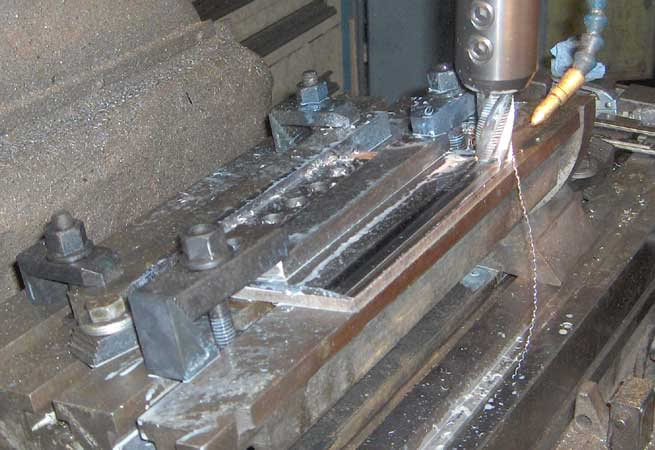 |
All fireside components have been manufactured from 316 stainless steel. Here part of one main burners is machined in the Grand Canyon workshops. © Sam Lanter |
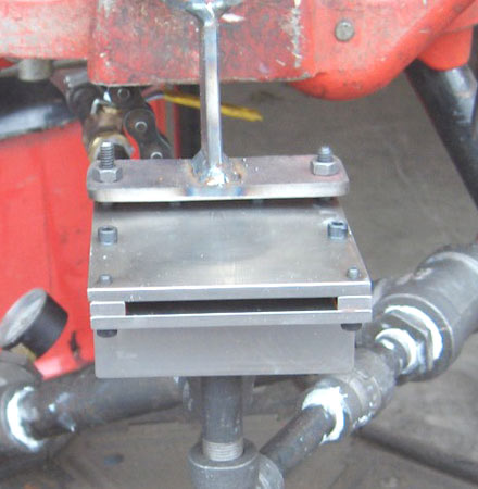 |
A close up of the 4" pilot burner prior to testing. © Sam Lanter |
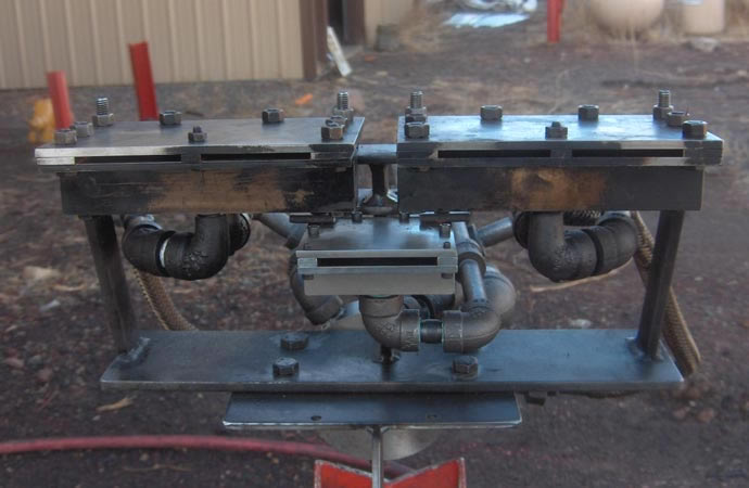 |
The completed oil burners rigged up for testing. © Sam Lanter |
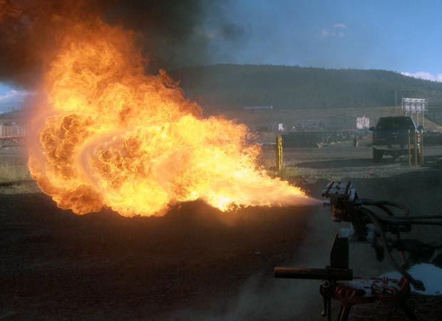 |
How to test an oil burner! Here the pilot burner is put through its paces. © Sam Lanter |
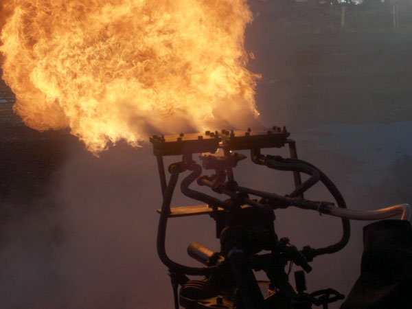 |
And testing the two 6" main burners! © Sam Lanter |
No.29 has been fitted with a pair of flat burners which fire from the front of the firebox. In addition, to give acceptable turndown ratios on the system as a whole, below the main burners a smaller pilot burner, essentially of the same design, has been fitted. The genesis of the system can be traced back to trials at Boston Lodge, on the Ffestiniog Railway, in the early 1990s. Since this time Nigel has moved away from such flat burners as he believes round flat burners (that is those emitting a flat flame over a 360° diameter) give better results. However the fitting of the flat burner to No.29 has be done for several reasons. Importantly it allows locomotives with old burners positioned at the front of the firebox, such as Weir burners and trough type burners, to be modified with the minimal of firepan and plumbing alterations. It will, in time, also serve as a comparison between this form of burner and the round flat type. Given this is the first application of either type of burner to really big locomotives there is a lot to prove and a lot of people to prove wrong!
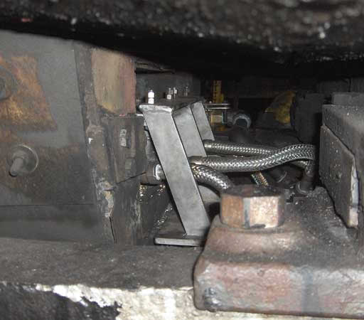 |
The burner has basically slotted into the firepan where the old burner was to be found with minimal modifications being required. © Sam Lanter |
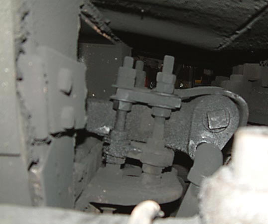 |
For comparison here is the old burner in position. August 2005. © Nigel Day |
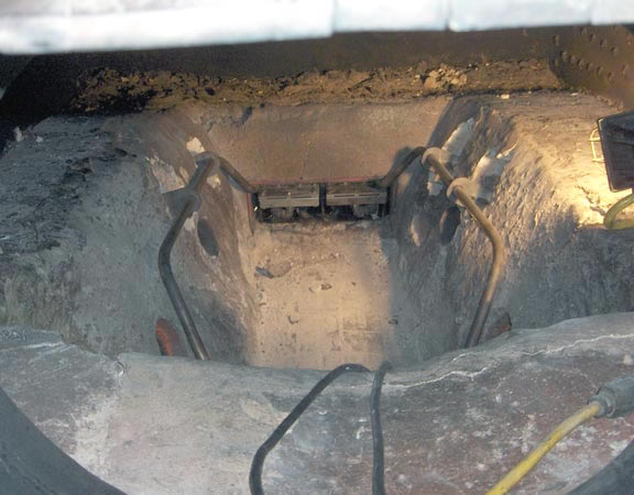 |
The firebox side view of the main burners in position with the pilot burner remaining to be fitted. Note the pipes on either side of the fireclay. These carry the atomising steam to the burners, in the process superheating the atomising steam to a high temperature. As with the burners these superheaters are made from 316 stainless steel. Also note the combustion air holes in the fireclay. © Sam Lanter |
Already results have been truly excellent. Performance has been much as Nigel predicted with nothing more than normal tuning up required. Those who said the system would not work away from narrow gauge locos have already been proved wrong.
A direct comparison with previously recorded fuel consumption is difficult, especially as the fuel type has altered. However a conservative estimate is that fuel consumption is down 12-15%. If more detailed figures become available I hope to be able to quote them in time.
Baldwin 2-8-0 No.4960 is to be modified in 2006.
This locomotive is to receive Nigel's preferred burner in the form of a round flat burner. Externally this appears much like a modified Laidlaw-Drew burner but internally it is a very different and much better system. As will be appreciated fitting of this type of burner will require more substantial modifications of the locomotive. Nigel is confident the effort will be more than worthwhile. When details become available they will be published here.