LVM800 - "Prometheus
Project"
A
Standard Gauge 3 Cylinder Compound 0-6-2t
Locomotora Vapor Moderna 800 - LVM800 - is a standard gauge 3 cylinder Porta-type compound 0-6-2t design for shunting and branchline use. It has its history in a design proposal produced for the Argentine Railways in 1986. However Porta's thoughts first turned to designing a thoroughly modern shunting and branchline locomotive back in the 1960s when working on the British 'Austerity' 0-6-0st type. It has long been considered that it is almost impossible to make a shunting locomotive efficient; LVM800 shows otherwise.
 |
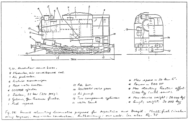
A 0-6-0t shunting loco for Argentine and Brazilian service - part of the history of the LVM800 concept. The drawing states "autonomy: one week". It is very interesting to note this machine has two inside cylinders, compounded on the Porta system, which would include resuperheating between the high and low pressure cylinders. The specification of inside cylinders with the added complexity this brings, especially for maintenance staff, can be explained by Porta's belief that careful and thoughtful detail design would render such issues unimportant. A truly well designed loco would not require day to day attention between the frames, much like an internal combustion engine does not need regular maintenance of the cylinder head components or crankshaft. There is a difference between intellectual complexity and actual complexity in a machine. Suggesting a machine should be as simple as possible in every way is an error of logic. |
The Design Concept and Philosophy
LVM800 was designed in the late 1990s and early part of the 21st century by Porta and a small team of Cuban engineers for Cuban service and conditions. Likewise it was designed with construction in Cuba in mind although other locations, which proved impractical for a variety of reasons, were also investigated. The project was known as the 'Prometheus Project' in Cuba. LVM800 has a continuous rating of 800hp when compared on a like to like basis with a diesel. Peak output would be higher at around 1000hp. 800hp was selected as it was felt to best match diesels then employed on similar tasks, these diesels generally having an engine rating of 1200hp. As the design developed, perhaps predictably, thoughts also turned to more diverse usage including suburban passenger services which in turn made the design of reciprocating components even more important than hitherto.
Writing in 1998, during the early days of the Cuban stage of the project, in his paper 'Some Aspects of the LVM800 Locomotive Design' Porta provided the following summary of the design:
"The LVM800 is a small shunting machine designed to burn a wide variety of fuels, amongst which biomass is standing in the first place. Some aspects deserve special comments:
(a) being a heavily ballasted machine, what happens when the fuel and water supplies are used? The answer is: these supplies allow a maximum low speed pull for a very small mass of elaborated metal. Should circumstances require to have, at all times, a maximum of adhesive weight, easy replenishment of the water tanks is to be arranged.
(b) stability at all speeds below a critical one (i.e.: guidance not relying on the flanges) it is assured by a number of design alternatives the behaviour of which can nowadays be predicted by computers.
(c) a complex thermodynamic cycle is a must to obtain high thermal efficiency. The Pennsylvania T1 is not the ROCKET. Intellectual complexity is to be differentiated from actual complexity: the user MUST have nothing to think about. Detail reliability is ensured by a well studied design, not by an "easy repair" when there is a failure.
The importance of thermal efficiency is appreciated in full when the design is compared to a simple expansion, traditional alternative. The lower thermal efficiency per force leads to a bigger machine (i.e. heavier mass of elaborated metal) which requires a tender to accomplish an equivalent autonomy, a 50% bigger boiler, 17% more adhesion weight, larger tanks and fuel bunkers etc. Incredibly, this viewpoint about thermal efficiency has never been spoken about.
The LVM800 is a product resulting from an interminable effort for the benefit of any customer."
As is normal the above is as written by Porta with minor alterations to the English. Any errors are that of the webmaster.
To the above can be added Porta's belief that even if the cost of fuel was to be zero it was incumbent on the design engineer to ensure maximum thermal efficiency. To some this must seem perverse, but it is not. It would allow the smallest machine possible thus ensuring the best power to weight ratio possible, it would use the smallest amount of fuel and water and so on. The consequence of which is that the resulting machine would be cheaper than a less efficient alternative.
Porta commented that for a locomotive of the output required a 0-4-0 type would have been possible but, thanks to modern steam technology, the resulting machine would have been so small as to be impractical - something akin to a "Coffee Pot" type locomotive. Increasing the size of the design gave the major advantage of increasing time between refueling and taking water. Estimated range is at least 200km between taking water and at least 400km between needing to take fuel. Such figures were estimated on maximum output at all times, not a normal way of operating. It should also be noted that standby losses, normally very high in shunting locos would be given very serious attention. Porta wrote of using "hyper-exaggerated" insulation, not "just" exaggerated insulation . |
 |
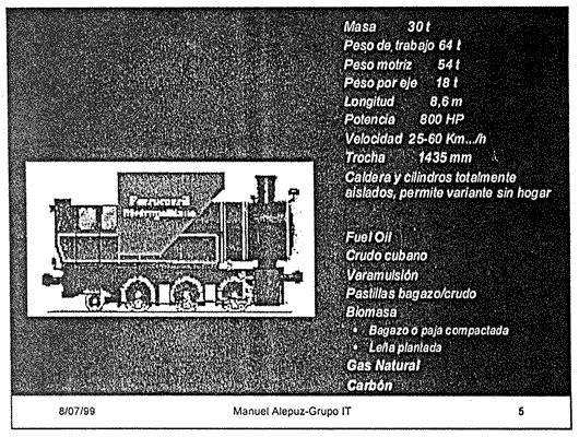 |
In 1999 the 'Ecovapor' Conference was held in La Habana, Cuba. Amongst the speakers was Manuel Alepuz. Sr Alepuz was key to the project. It is, perhaps, not a surprise that after his death the project fizzled out. On the left is a copy of one of the slides from his presentation. The copy is from a photocopy several generations old, hence the low quality, but it is included here for its interest. The lack of cab roof is assumed to be due to the photocopying process! |
The Alternative
Porta presented an alternative to LVM800 as a way of showing why he proposed a 6-coupled 3 cylinder compound over the best alternative he could conceive. This alternative was a 0-8-0 2 cylinder simple with the same rated output, tractive effort and autonomy.
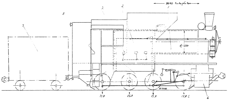
The alternative to LVM800 - a 2 cylinder simple 0-8-0t+t. Click here for an enlargement.
The details of this 0-8-0 are:
The Alternative 0-8-0
Specifications |
|
| Continuous Output | 800hp (596kW) |
| Maximum Boiler Pressure | 25
bar (362psi) |
| Maximum Rated Evaporation | 7500kg/hour (16535lb/hour) |
| Maximum Piston Thrust | 27000kgf |
| Nominal Tractive Effort (at 85%) | 18000kgf (39683lbs) |
| Driving Wheel Diameter | 1000mm |
| Range based on water capacity | >200km |
| Range based on fuel capacity | >400km |
As the alternative is a simple and thus less thermally efficient the resulting machine has to be larger to have the same output. This also means that more fuel and water is required to give the same period of autonomy - more fuel and water is used to produce the same output. So the fuel bunker and water tanks have to have a greater capacity. Porta quoted the expected thermal efficiency of the 0-8-0 to be 10% whereas for LVM800 it would be 15%.
To make up for the very much lower year round thermal efficiency the following where found, by calculation, to be necessary:
No economiser is fitted as there is not the room without further extending the chassis. Likewise there is no room for a combustion air preheater.
Whilst the boiler pressure is 25 bar the cylinders would receive steam at 18 bar for a number of reasons the reader is left to consider.
An alternative to the alternative would be a 2-8-2t version capable of carrying all fuel and water onboard. The wheel arrangement would further limit the minimum radius curve the design could successfully negotiate - often an important factor in yards.
LVM800 Design
When writing about LVM800 Porta said ".... (there are) some particular areas in which one is notoriously as odds with current opinions." But then what else would be expected?
This locomotive is essentially designed and awaits a builder with only a handful of items needing to be finalised, an easy task for anyone who understands Porta's technology and philosophy. A number of designs prepared by Porta in the 1970s are in a very similar state of completeness with reference being made to these or other work undertaken to show how certain items should be completed. Designed for Cuban conditions and manufacturing capacities some of LVM800's features could be different if constructed for use elsewhere.

LVM800's general arrangement drawing as in 1998. For an enlargement click here.
The locomotive's physical limiting dimensions, as designed, are: Length: 8600 mm, Width: 3000 mm, Height: 4600 mm.
LVM800
Specifications & Statistics |
|
| Continuous Output | 800hp (596kW) |
| Maximum Boiler Pressure | 25
bar (362psi) |
| Working Boiler Pressure | 20 bar (290psi) |
| Grate Area | 1.8m² |
| Heating Surface | 40m² |
| Firebox Volume | 3m² |
| Maximum Rated Evaporation | 5000kg/hour (11023lb/hour) |
| Maximum Piston Thrust | 17000kgf |
| Nominal Tractive Effort (at 85%) | 18000kgf (39683lbs) |
| Driving Wheel Diameter | 1000mm |
| Range based on water capacity | >200km |
| Range based on fuel capacity | >400km |
 |
General Arrangement drawing details for LVM800: 1. Fuel space (6m3) |
The Chassis & Cylinders
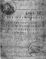 The frames are of the bar type welded, not bolted, together. Any distortions in the frames due to manufacturing was considered, by Porta, to be unimportant. By using the Poissonnier method of lining up such imperfections can be easily overcome. Porta, who received a copy of this SNCF procedure from Monsieur Poissonnier personally in October 1952, felt it was the best system developed for lining up frames and related components. This includes being better than the well known optical lining up systems favoured in many parts of the world. Porta considered it was possible to come to a more accurate result with the Poissonnier method. Whilst a cast steel bed might be considered the pinnacle of locomotive frame construction Porta's view was that they were unnecessary for the reasons explained in this paragraph not to mention the high cost of production.
For items not to be welded to the chassis nuts, bolts and studs of commercial, "off the shelf" type are not acceptable - poor manufacture makes them liable to loosening in service. So these items would be specially made for the job. However, when possible, items are welded to the chassis rather than bolted. In many ways methods of structural construction and ruggedness owe more the the marine engineering world than railways where welding has been used to overcome many problems.
The rear truck has Cartazzi side control. The wheels are a welded fabrication rather than a cast design, shrunk on to the axle eliminating the need for heavy pressing and the manufacture and fitting of a key.

A general sketch of LVM800's bar frame arrangement as drawn in 1998. It shows some differences from the general arrangement drawing above but as this is more complete it is likely it supercedes the general arrangement.
The 1000mm diameter driving wheel centres are also welded fabrications with the hub being a steel forging all, again, shrunk on to the axle. Final design data is not to currently to hand, however tentatively the crank pins were set at 120° angle to each other. The final design calculations will have determined the optimum crank angle. If not 120° it would only be different by a few degrees either way.
The Beugniot system of coupled axle steering is used to assist the type in going around corners, especially sharper ones. The use of tread steering (the profile of the tyre) also makes a considerable contribution to bother steering and also stability in general.
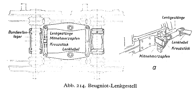
The Beugniot axle steering system as scanned from a German language book.
Roller bearings are of course the preferred option but the best of former plain bearing practice was an option for reasons of cost not performance. However it should be remembered that plain bearings fitted to the Rio Turbio 2-10-2s gave excellent service in extremely harsh operating conditions.
The driven axles have Libertad automatic wedges, a system developed from the well known Franklin type of spring loaded wedge. An alternative considered was to do away with such systems totally and introduce the Cario axlebox scheme - this would have been quite a radical departure and is a subject deserving of a separate webpage. It is assumed it was not adopted as it had never been tried out on a locomotive before. Whilst LVM800 breaks new ground the result is largely predictable in its current form, being based on previously undertaken work, whereas a technology such as Cario would have increased the risk of serious problems by quite some amount.
Naturally the chassis suspension is fully equalised despite the relative lack of room available. To think of a modern steam locomotive without fully equalisation is unthinkable!
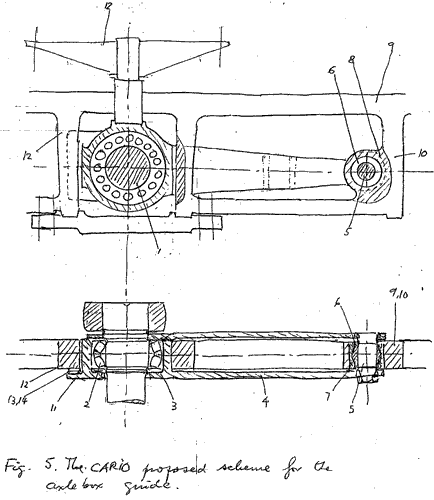 |
The Cario arrangement for axlebox guides - very different to the traditional arrangements! This drawing is taken from Porta's January 2000, unfinished, paper "Cario: An Advanced Axlebox Scheme for XXIst Century Steam Locomotives" 1. Axle. |
Connecting and coupling rods are, naturally, as light as possible to reduce the effects of unsprung masses on both the machine and track. A Dean type of crosshead and crosshead slipper arrangement is specified. Fischer knuckle pins, which eliminate fork breakage at coupling rod connections, are used.
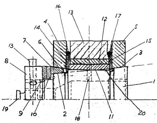 |
The Fischer Knuckle Pin 1. Pin. |
Adhesion
Sanding equipment is specified in line with the best available including sanding of the rear truck - item 15 on the general arrangement drawing is the sandbox for the rear truck. The purpose being, as Chapelon showed in the 1930s, to allow the undriven wheel to condition the railhead prior to the driven axles passing over it. Only a very small amount of sand is required to eliminate the need to sand the driven axles in all but the worst adhesion conditions. The leading and trailing driven axles are sanded. The sand boxes are of sufficient size so as to not need re-filling on a daily basis. When sand is put down a rail washer is also activated to ensure sand does not get onto the tyres of the vehicles following increasing their rolling resistance. An important aspect of sanding system design is to keep the sand delivery lines as short and as direct as possible.
 |
A sand trap design from Porta's 1990 paper "Steam Locomotive Power: Advances made During the last Thirty Years. The Future." Porta's comments accompanying this diagram are: "Proposed sand trap incorporating all the best features gathered from practice. Adhesion is so important it deserves close attention to detail". In other words on all Porta locos, unlike so many, sanding was not to be an after-thought! |
Naturally, in addition to the best sanding possible, the driven axles have the high adhesion wheel profile the design of which also dictates that the driven wheelset (as opposed to the coupled driven wheelsets) has a 3mm greater diameter from new to take up for the fact this wheelset wears faster than the others. Regular tyre grinding (not turning) is part of the maintenance plan. As part of the work leading up to the design of LVM800 Porta and his team had further advanced the design of the high adhesion wheel profile on test loco Minaz 1816. This profile has also been applied to the locomotives at FCAF, Ushuaia, Argentina.
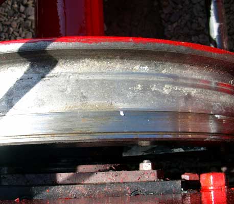 |
High adhesion wheel profile as applied to FCAF No.2. October 2004. |
If built today it can now be assumed that LVM800 would also be fitted with railhead cleaning jets, as first used on FCAF locomotives. This system fires live steam at the railhead to blast away contaminants. Having seen the system in use the writer can testify to its success in improving adhesion and removing the need for sanding. The use of such a system helps to demonstrate a point Porta used to make - that railhead conditioning is vitally important. Put another way sanding should be the last resort when all others have failed, first contamination of the railhead should be prevented wherever possible after which various methods can be engaged to remove contaminants.
It can also be assumed that another feature of the FCAF locomotives, condensed steam flange lubrication would be used. This system uses only condensed pure steam, no oils or greases to lubricate the flanges of the locomotive. The water on the railhead also acts as a lubricant for the wheels of the train, something which, again, the writer witnessed working extremely well on FCAF.
Further details on adhesion aids can be found here.
The Boiler, Fuels and the Combustion System
To those not accustomed to modern steam locomotive design and thermodynamics the boiler appears relatively small for the output required of it, but it is not. This is yet another common feature of Porta locos going right back to his very first, 4-8-0 4 cylinder compound 'Argentina'. When it is considered the average North American loco lost up to 25% of its rated evaporation past ineffective piston and valve rings (that is 25% of the steam produced was wasted, it produced no work whatsoever) it starts to rapidly become clear how attention to detail makes it possible to use considerably smaller boilers than hitherto. This is before issues of boiler efficiency are addressed which only serve to reduce the size required even further. The size of the boiler underlines an often overlook fact - the steam locomotive is a heat engine first and a mechanical machine second.

This drawing has been produced to highlight the small size of the LVM800's boiler and compare it with the boiler of Porta's alternative - the 0-8-0t+t 2 cylinder simple. The boiler for the later is considerably larger as is the firebox. In the case of LVM800 the overall cycle efficiency of the design results in a small boiler barrel which allows a lengthy smokebox. This creates room for the economiser which has to be dispensed with in the simple due to a lack of room. The relative height (volume) of the firebox on LVM800 also stands out. This is so designed to ensure excellent combustion. The grate area to firebox volume ratio is somewhat smaller on the simple locomotive which would make it harder to ensure excellent combustion. Despite LVM800's small boiler barrel calculation shows the desired peak superheated steam temperatures of 450°C for the high pressure cylinder and 400°C for the low pressure cylinders could be achieved.
Boiler pressure is set at 25 bar (362psi), almost certainly a record for a shunting loco. The boiler design is in line with the very best of the German TUV codes incorporating Porta's own advances on the German work. Coupled to the use of 'Porta Treatment' to ensure water side surfaces totally free of fouling and corrosion the old arguments about boiler pressure increases leading to increased maintenance costs can be dismissed. The ability to guarantee zero water side fouling also allows the tube spacing to be altered from the traditional thus meaning more tubes can be installed in a given diameter of boiler. Like any boiler, at the rear end it sits on slides attached to the frames to allow for expansion. At the front it is welded to the frame. With water treatment guaranteed to keep the internals of the boiler in as new condition way beyond the economic life of the locomotive Porta felt there was no need to make the boiler a removable item.
Originally designed for use in Cuba and at sugar mills the obvious fuel to select was bagasse. Bagasse is a waste product of the sugar cane industry, an industry which used to be a major part of the Cuban economy. The failure of this locomotive to be built can be linked to the decline of the Cuban sugar industry, a result of a collapse in the international price of sugar. Being an external combustion locomotive alterations allowing the clean and efficient combustion of virtually any fuel is possible. As designed the firebox is configured for the Cyclonic Gas Producer Combustion System (C-GPCS). As such the boiler is mounted relatively high allowing maximum firebox volume above the frames helping to make combustion as good as possible. Fuel sits in the bunker on top of the flat topped firebox (to use a round topped firebox would be a mistake for several reasons including the constricted steam space) with it entering the firebox via the fuel inlet holes (item 18 on the general arrangement drawing). Whilst initially such "side firing" might seem unusual it isn't unique. The double-Fairlie type is fired from the sides. In addition a more traditionally placed firehole door is provided but is not normally used. Fuel enters the firebox under the control of the fireman by a combination of gravity, the use of rams (a form of technology copied from other branches of industry) and with the final fuel distribution within the firebox being via a modified Elvin type stoker head. The system helps to achieve the desired for "washbowl" shape of fire - that is thicker at the edges than in the centre. However this doesn't necessarily mean a thin fire in the centre - being a gas producer a relatively thick fire is required over the entire grate. The grate type is the standard fully rocking pin hole type. The V-anti-clinker, grinding type of grate was not selected.
Whilst is is unlikely a Cuban LVM800 would ever have been single manned the locomotive was designed from the outset to accommodate this with the fuel delivery system being one aspect so designed.
Combustion air is routed via a preheater, located in front of the firebox and between the frames, to raise its temperature as high as possible thus reducing the energy lost from combustion heating the nitrogen in air. Nitrogen, being an inert gas, plays no role in combustion despite making up 79% of a typical air sample. The preheater is supplied with a percentage of exhaust steam from the cylinders. From the preheater the combustion air is ducted to the ashpan to form primary air and to the overfire airholes forming the secondary air so crucial for good combustion with the Gas Producer Combustion System. By the time of LVM800's design Porta had come to favour placing the overfire airholes in the front and rear of the firebox, not the sides as had been his normal practice until the late 1980s/early 1990s. Naturally some secondary air also enters the firebox via the firing inlets but the bulk is via the very carefully positioned and sized overfire airholes.
This diagram shows the essence of the Cyclonic Gas Producer Combustion System Furnace. The diagram relates to an earlier Porta design so LVM800 has detail differences but the general concept is the same. In Cuban form LVM800's firebox is not round but this remains an option should the locomotive be built elsewhere. |
 |
As is shown in the Alepuz presentation slide towards the top of this page the locomotive was not only conceived as a bagasse burner. Again, typical of Porta, it is designed to be a multi-fuel locomotive. In essence this means that it could rapidly be converted to burn a range of fuels. These include:
As will be appreciated adapting the loco to burn some fuels will be easier than others - for example a move from one solid fuel to another is going to be easier than a move from a solid fuel to a liquid. That said the locomotive is arranged so that the changeover requiring the most work could be completed within one working day. So, for example, if changing from solid to liquid fuel the rocking grate does not need to be removed piece by piece but as one complete item and so on.
Naturally a CO2 neutral fuel would be the overall preference but the above list, which is not exhaustive, goes some way to showing the flexibility of the steam locomotive. No longer need a railway be tied to a single fuel source for life which offers significant advantages such as the ability to change fuel as availability or price changes. That's not so easy to do with an internal combustion machine.
As will have been seen the early versions of what became LVM800 were specified as 0-6-0t machines whereas LVM800, as designed for Cuban conditions, is a 0-6-2t. The trailing axle was added at the request of the Cubans to allow logs to be carried as fuel in the bunker behind the cab. Unlike the fuel stored in the bunker over the firebox, firing on logs would be by hand. Thus the design incorporated, from the outset, the ability to be a multi-fuel machine.
Another very typical Porta feature is that of raising the front of the firebox crown above the height of the bulk of the crown or at least that is how it looks. In reality the crown is actually depressed below the level that would otherwise be expected. This feature was first incorporated in a locomotive boiler back in 1949. It allows extra tubes to be included in the tube bundle without radically reducing the steam space above the firebox crown.
 |
Not LVM800 but the principle is the same. The depressed crown/raised front portion of the firebox crown allows an extra row of flu tubes to be installed. Also note the upper section of a T circulator. Item 4 in the drawing is a directional vane to control water circulation. |
A single Lempor exhaust ejector is specified but for locations with restricted loading gauge Porta recommended use of the Lemprex system (subject to finalisation of the design.)
Roughened smoke tubes (fire side) are used whilst the superheater and re-superheater elements are roughened on the fire side to ensure maximum heat transfer rates. The flu tubes have a plain fire side as the primary purpose of flus is to superheat the steam not to assist in boiling water. See here for more details of roughened tubes.
The Feedwater System
To ensure maximum efficiency both a closed type feedwater heater and an economiser are specified. Both make use of heat that would otherwise be wasted - specifically exhaust steam and combustion gases. Only heat that would be wasted due to the nature of the thermodynamic cycle is used, as is correct thermodynamically. Heat that is wasted for other reasons is not used, rather every effort is made to make sure it is not wasted! This would include minimising losses from the boiler by ensuring it is very heavily insulated.
The feedwater heater is fed with exhaust steam from the low pressure cylinders only. The heat exchanger is situated on top of the smokebox behind the diffuser. However the use of feedwater heating alone was insufficient for Porta. To gain the maximum feedwater temperature and thus maximum thermodynamic benefit (which means less fuel and water per unit of power and a locomotive with a higher sustainable output) an economiser is incorporated. This is upstream of the feedwater heater and is situated ahead of the front tubeplate and behind the exhaust system. Basically the economiser is a large heat exchanger which makes use of the residual heat in the combustion gases to further increase the temperature of the feedwater passing through. The fire side of the economiser tubes are roughened to increase the rate of energy transfer.
Some of the reasons justifying the use of this form and location of economiser are:
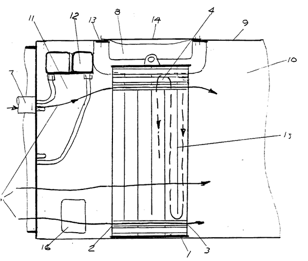 |
An economiser showing the general location in the smokebox, the gas flow and the water flow. As would be expected the feedwater, which has already passed through the closed feedwater heater enters the economiser at the smokebox door end (where the combustion gases will be at their coolest) traveling backwards towards the tubeplate before being directed into the boiler. The item labelled 14 on the drawing is a cover on the smokebox to allow easy access and removal. The very low rates of firebed particle entrainment coupled to an all welded boiler designed to the highest standards and using 'Porta Treatment' means access to the tubeplate would only be required very infrequently and certainly not on a daily basis. If it were the economiser's location would be impractical. However an access cover, number 16 on the drawing, is provided for inspection purposes. |
The feedwater system is driven by Knorr pumps adapted to use superheated rather than saturated steam. However, going back to a technology considered long forgotten, a motion driven water pump is also specified. The pump is based on a modified air brake pump.
The feedwater enters the boiler below the normal minimum water level - that is the feed is submerged. Top feed, whilst good at removing oxygen in the feedwater, promotes scaling at the physiochemical level. By using a submerged feed this tendency is overcome. The chemicals in the water treatment make sure that the potentially negative effects of dissolved oxygen in the feedwater are prevented.
 |
LVM800 in Cuban form. © H.G.Kagi |
The Steam Circuit, Cylinders and Compounding
The throttle valve is on the hot side of the superheater header. This provides better fine control of the locomotive, means that superheated steam is available "immediately" (peak temperatures can only be achieved after a suitable period of warming up) and also allows superheated steam to be provided to auxiliaries thus improving their efficiency.
Maximum steam temperature in the high pressure (HP) cylinder is 450°C, with lubrication being assured by advanced tribology. The steam circuit from the HP cylinder exhaust leads to a resuperheater ensuring that the two low pressure cylinders receive steam at 400°C. As can be envisaged such rates of superheating and resuperheating mean the vast majority of the boiler barrel (75% of the cross sectional area) is taken up with flu tubes rather than smoke tubes.
The locomotive is equipped with a 3 cylinder compound engine of the Porta type. The high pressure cylinder (440mm x 550mm) sits in between the frames with the 2 low pressure cylinders (512mm x 550mm) on either side of the locomotive. All cylinders are fabricated, not a single casting is required for LVM800. As is normal for Porta type compounds Southern valvegear is specified. Porta rejected the normal list of objections to Southern gear, in part because of the advances in technology made since the heyday of steam which renders these objections void, something very few people seem to be able to understand. So fairly typical of Porta technology!
Starting the locomotive is via the automatic system Porta first used in 1949. There is no need for the driver to operate a manual starting valve or use any other method.
Being a 3 cylinder locomotive naturally dictates the use of a crank axle. This is the centre driven axle, which is also driven by the outside cylinders . The crank axle is of the built up type, designed in line with AAR specifications. There are no requirements for forging of components as in the past. As noted above final design information on the angle of the cranks is not currently to hand.
As would be expected with a Porta locomotive poppet valves are not to be used, rather the Porta-type lightweight, articulated multi-ring piston valves are used, as proven in service time and time again since 1949. Just some of the reasons for not using poppet valves include a totally unacceptable lack of steam tightness (high steam leakage rates), the fact much of the equipment is very high precision (so not heavy duty or especially reliable as well as being expensive to manufacture) and they are complicated to set up and maintain. Porta wrote many hundreds of pages of highly technical reasoning on why, overall, piston valves are better than poppet valves most of which is very in depth and too complicated for a page such as this!
 |
A Porta type lightweight, articulated multi-ring piston valve. This particular valve design was used on David Wardale's 'Red Devil' (SAR Class 26 No.3450) but the principle is identical for LVM800. The valve is a fabrication to help reduce the weight, the articulation takes up unevenness in the drive and or lining up of the bore and motion whilst the large number of narrow rings, of diesel engine quality, ensure maximum steam tightness with a considerably reduced specific bearing pressure. Such a valve can be expected to remain steam tight for several hundred thousand kms of use. |
All the piston heads are welded to the respective piston and tail rods thus removing yet another problem area in traditional locomotive designs. Readers are referred to David Wardale's comments on the problems associated with not having a welded piston and piston rod assembly. Brims are welded to the piston heads in the low pressure cylinders to reduce clearance volumes, which reached about 5%. This is not necessary with the high pressure cylinder piston. Naturally, these brims are hollow to keep the mass of reciprocating parts to an absolute minimum.
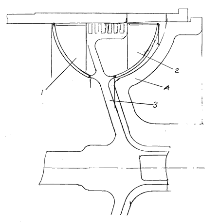 |
An all welded piston assembly including brims to reduce the clearance volume as used on the low pressure cylinders of LVM800. 1 & 2. Hollow brims. |
The valvegear for the high and low pressure engines are linked together so there is only one reverser to control.
More information of the Porta type of compounding can be found in the book "Advanced Steam Locomotive Development - Three Technical Papers" published in 2006 by Camden Miniature Steam Services. |
 |
Performance
Rated continuous output is 800hp with a peak output as high as 1000hp.
One interesting set of features included in the design were first used by Porta on FCGB No.1802. The pressure gauge on the locomotive has a green line and red line. The green line is at the normal maximum working pressure of 20 bar. The fireman is instructed to manage the boiler so that pressure is maintained as close to the green line as possible. Lifting the safety valves is, obviously, a waste of energy (money) and thus something to be avoided if possible, hence the concept of working to the green line. On LVM800 (and other Porta type locomotives) the red line is at the absolute maximum permissible boiler pressure allowed under the ASME boiler codes. In this case the safety valves are set to lift at 25 bar so the red line on the pressure gauge is at 25 bar. When extra power is required the option is there to use the reserve increased the boiler pressure.
The green line/red line working is coupled to a specially arranged throttle valve. The valve, on opening, first has a drifting position (to provide a breath of steam to prevent the formation of a vacuum in the cylinders, as for all Porta type locomotives drifting is in midgear), followed by a couple of fixable positions for moving the locomotive around light. After that the only other position the throttle valve locks at is the normal fully open position (enforced full throttle working) - thus helping to ensure working in the correct thermodynamic way (maximum steam chest pressures with all of the corresponding steam having passed through the superheater and resuperheater elements. Power adjustment is controlled by altering the cut off.) At the normal fully open position the throttle valve will allow the full 20 bar boiler pressure into the steam circuit. If the throttle is not locked in the normal fully open position it is arranged to drop back to one of the light engine stops. However the throttle is also arranged to open further to the true full throttle position, a position at which it has to be held open against, if not it will drop straight back to the normal fully open position. In this position the throttle valve allows 25 bar to enter the steam circuit. This might sound very odd but can be compared to being able to work a diesel or electric locomotive beyond its normal maximum amperage (needle in the red). In such circumstances the locomotive can be worked at this rate for a certain specified rated period of time only. In the case of LVM800 the true full throttle position provides an extra opening of the throttle valve which allows the locomotive to be worked beyond its maximum rated boiler evaporation. This is in preference to working the locomotive with a longer cut off which is thermodynamically less efficient and can lead to a cylinder saturation effect. This arrangement can be seen as a form of booster but one that does not require heavy equipment, that is normally nothing more than dead weight, to be carried on the locomotive, amongst other disadvantages.
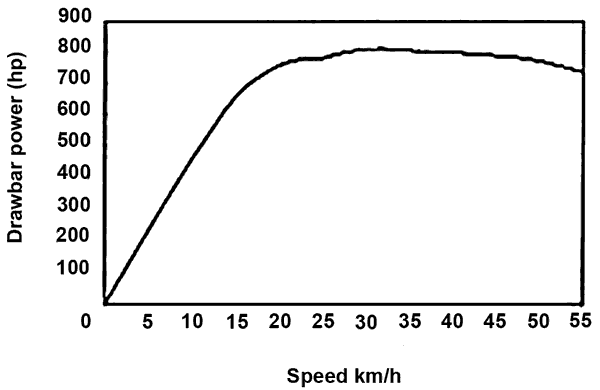 |
Drawbar horsepower against speed for LVM800. This graph is based on expected continuous output and not maximum output at any given speed. |
Tractive effort against speed for LVM800 - based on normal operating conditions and thus not taking into account the "extra" power available with the throttle value described in this article. |
 |
Another part of the LVM800 concept history, another 0-6-0 2 cylinder Porta type compound. Being very similar in most features to the loco shown at the top of this page one interesting alteration is the specification of outside Stephenson valvegear. Porta normally favoured Southern valvegear for his compounds, rejecting the normal list of objections presented against the use of this gear. The drawing is, sadly, not dated. |
 |

A Cuban 3D rendering of LVM800 part way through the design process. As would be expected it shows some differences to the outline general arrangement drawings produced in 1998. Clearly the above is incomplete but shows some features of the type - notably the very long travel valves and also more details of the arrangements for fuel delivery.
en español: Tracción a vapor moderna y sostenible – el escenario cubano
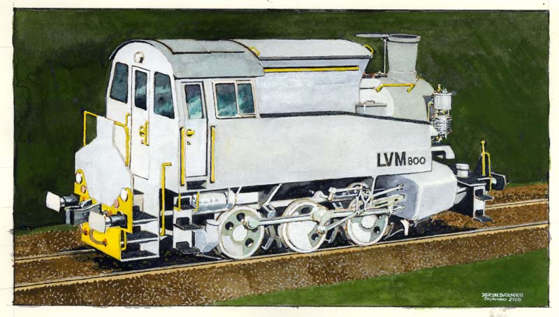
In 2008 artist Robin Barnes was commissioned to paint a pair of speculative views of LVM800 as adapted for European use. Naturally these paintings are not highly detailed or exact engineering renderings of the locomotive but none the less give an excellent impression of one possible configuration. As can be seen the locomotive has been returned to 0-6-0 format as it was felt there would be little need for the rear fuel bunker. This change also introduced other possibilities as shown along with some more recent thinking on how the locomotive could be. My thanks to Robin Barnes for producing such excellent paintings and being patient with all the alterations made during the initial stages of the work!

"What I don't understand is necessarily wrong." - Brazilian "Office Theory".*
* Perhaps it is worth adding to this statement "and the person reviewing something needs to have the intelligence to realise they don't or can't understand something."
References:
Olmo, J.: Tracción
a vapor moderna y sostenible – el escenario cubano. Undated copy.
Porta, L.D.: The Fischer Knuckle Pin in Advanced Steam Locomotive Engineering. 1986
Porta, L.D.: Some Aspects of the LVM800 Locomotive Design. 1998
Porta, L.D.: On the Possibility of Manufacturing the 800 HP LVM800 Steam Locomotives in Cuba. 1998
Porta, L.D.: Steam Locomotive Power: Advances made During the last Thirty Years. The Future. 1990
Porta, L.D.: Fundamentals of the Porta Compound System for Steam Locomotives. 2000 (Also see here.)
Porta, L.D.:Cario: An Advanced Axlebox Scheme for XXIsst Century Steam Locomotives. 2000
Porta, L.D.: Steam Locomotive Power for the XXIst Century. 2001.
Various e-mails & meetings between the webmaster and McMahon, S.T. 2006-2008
Various e-mails and discussions between the webmaster and Ramos, M. 2005-2008